Project Spotlight:
Service Water Piping Rehabilitation – Safety Related
Introduction
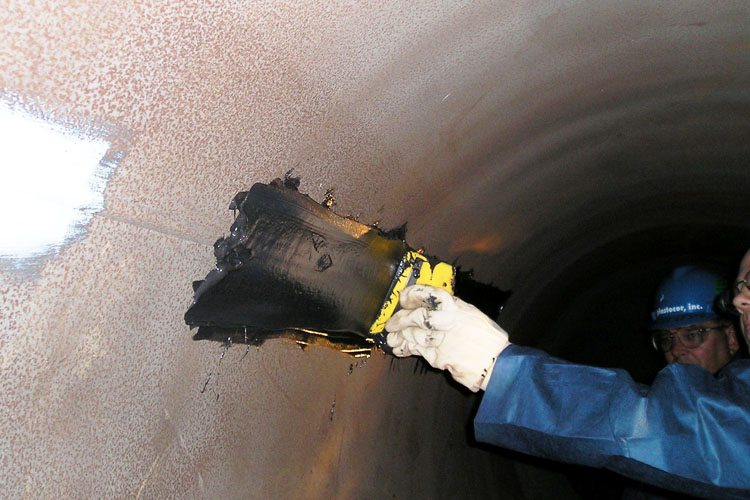
First put into service in 1985, the service water piping at a nuclear power plant was experiencing corrosion that was approaching the minimum wall thickness for the pipe. The pipe was made of unlined carbon steel. The worst of the corrosion was occurring at the weld seams.
The cost of replacing the piping with new carbon steel had been estimated at approximately one billion dollars. A variety of alternatives were considered, with the ultimate decision made to protect the pipe with an epoxy lining system designed to both rebuild and protect the pipe.
The service water supply system at a nuclear facility is safety related, so options were limited to ASME code restrictions and Appendix B guidelines.
System Description:
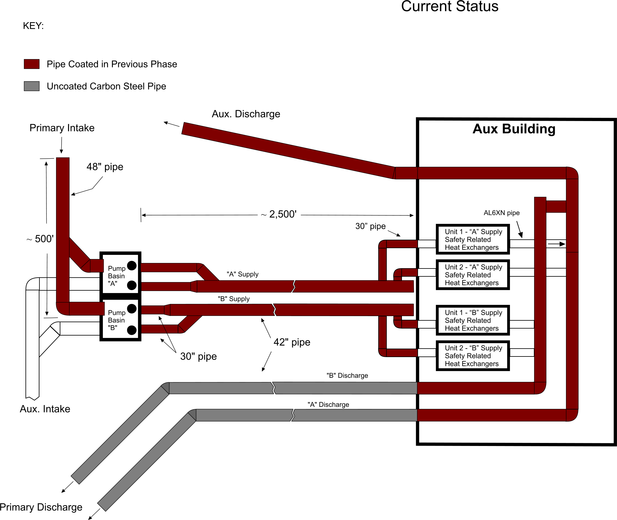
The piping system consists of two independent supply lines (“Alpha” and “Bravo”) which split into two trains at the pump house. Each train is powered by two pumps. Each of these trains can serve either of the two generating units located at the facility. A simplified schematic of the system is shown in the figure below.
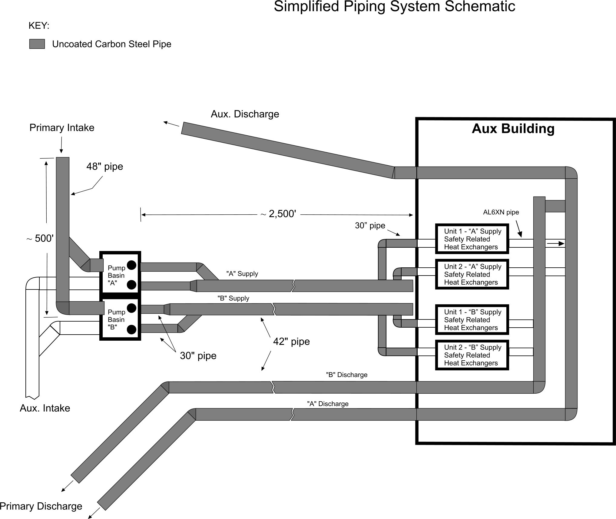
Schematic of Service Water System
Coating Selection:
Research into coating solutions started in 2002-2003 in two specific areas:
1) Selection of a coating system which would represent a permanent lining system. Target characteristics of the system were:
-
A service life of at least twenty years with minimal maintenance in order to accommodate re-licensing horizons.
-
Proven track record in the Nuclear industry.
-
Superior physical characteristics such as adhesion and durability.
-
Ease of repair (if required)
2) Selection of a coating which would protect the weld seams. Target characteristics of the system were:
-
That it can be applied in a single coat up to 1/4” thickness to fill pitted steel
-
That after limited cure time, the water flow could be started, and the product would continue to cure underwater. This was a contingency criterion to assure that LCO times were not violated.
-
period while the piping system is reconfigured.
-
That it be compatible with the permanent Plastocor system which would be applied later on top of it.
After careful consideration, the Plastocor Epoxy Cladding System was selected at a thickness of 75 mils for the permanent coating system to be installed. This system features a virtually flawless performance on power plant cooling water systems dating to 1984. In addition, the system has extensive experience on both safety related and non-safety related applications within the Nuclear Industry.
For the weld seams, the material selection was the Duromar SAR UW at a DFT of 125 mils. This selection was made after the utility and Plastocor concluded a testing program in 2003. This program was conducted to confirm that the material met the required criteria. The Duromar SAR UW is supplied by Plastocor and also has an extensive track record with nuclear cooling water systems.
Project Time Constraints:
Because the Service Water Supply System is safety related, it is subject to redundancy requirements. The supply piping to the pump house is fully redundant whereby two separate pipe intake systems were able to supply both trains at the pump house. This meant that one supply line at a time could be taken out of service and lined with minimum time restraints. As for the two trains running from the pump house to the Auxiliary Building, while they are redundant to one another, this redundancy is dependent on the successful operation of two isolated pumps supplying each train. This meant that taking a single train out for service could only be done under a 14 day LCO (Limited Condition Operation).
Pre-Project Mock-Up:
Prior to commencing with the project, a mock-up of 400′ of 42″ carbon steel pipe was fabricated. This mock-up included a “T” connection with 100′ of 30″ pipe. The whole system was buried to replicate actual coating conditions. The purpose of the mock-up was twofold: 1) give the contractors and associated personnel a training aid and 2) serve as a dry run for the actual work. The mock pipe and practice application activities are shown in the pictures below.

300′ Mock-Up of the Pipe
Practice Application on Weld Seams of the Mock-Up
Project Phases:
In order to accommodate time constraints, the project was divided into six phases which were executed over an eight year period.
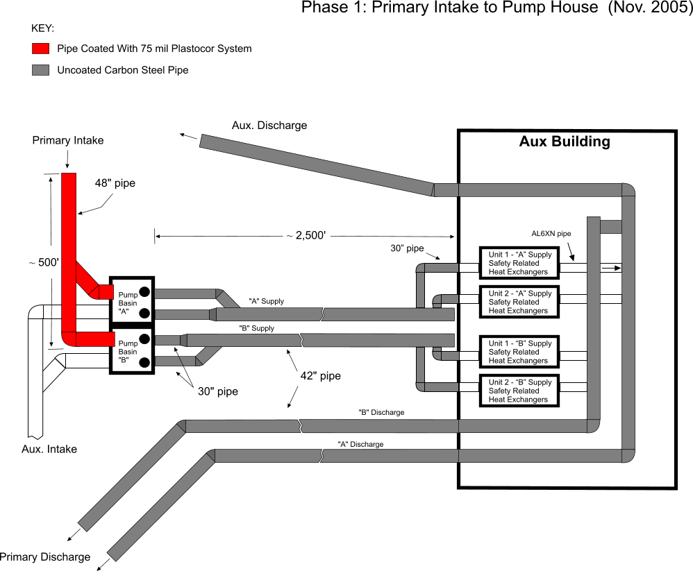
Phase 1 (November 2005): In the first phase, one of the two supply lines going to the pump house was taken out of service and coated.
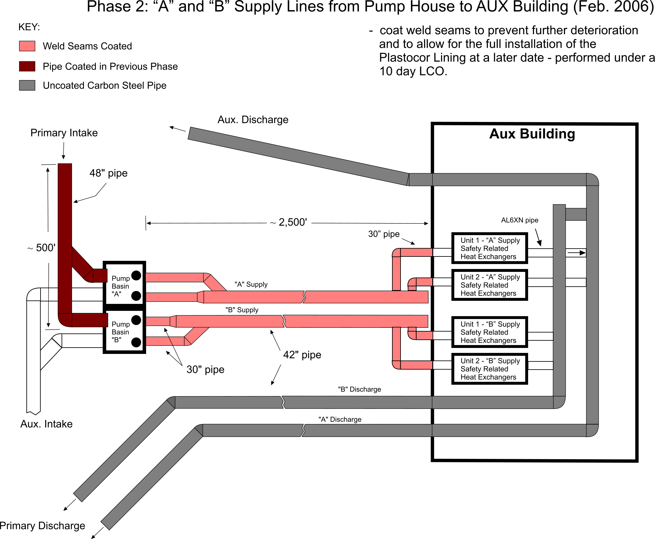
Phase 2 (February 2006): Each of the Alpha and Bravo supply trains were nearly half a mile in length and it was not feasible to fully coat them during a 14 day LCO. Since the welds showed the most serious deterioration, it was decided to just coat the weld seams during two separate 14 day LCOs. This then allowed time for the whole system to be reconfigured so each of the four pumps could feed both the Alpha and Bravo trains. This reconfiguration would create a fully redundant condition so that future work on these trains would not require a LCO. The complete lining system was subsequently installed four years later. (Phase 5 : February 2010)
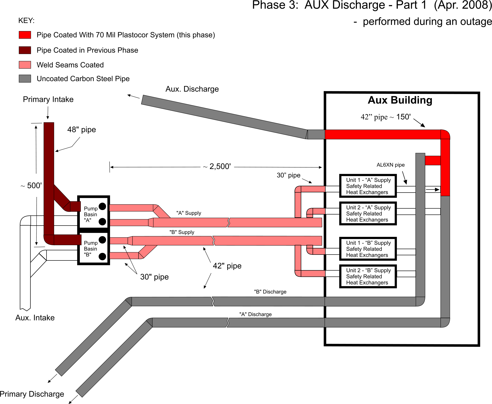
Phase 3 (April 2008): For Phase 3, the focus was shifted to the auxiliary discharge pipe located within the Aux. building. Here 150′ of 42″ diameter pipe was coated during an outage.
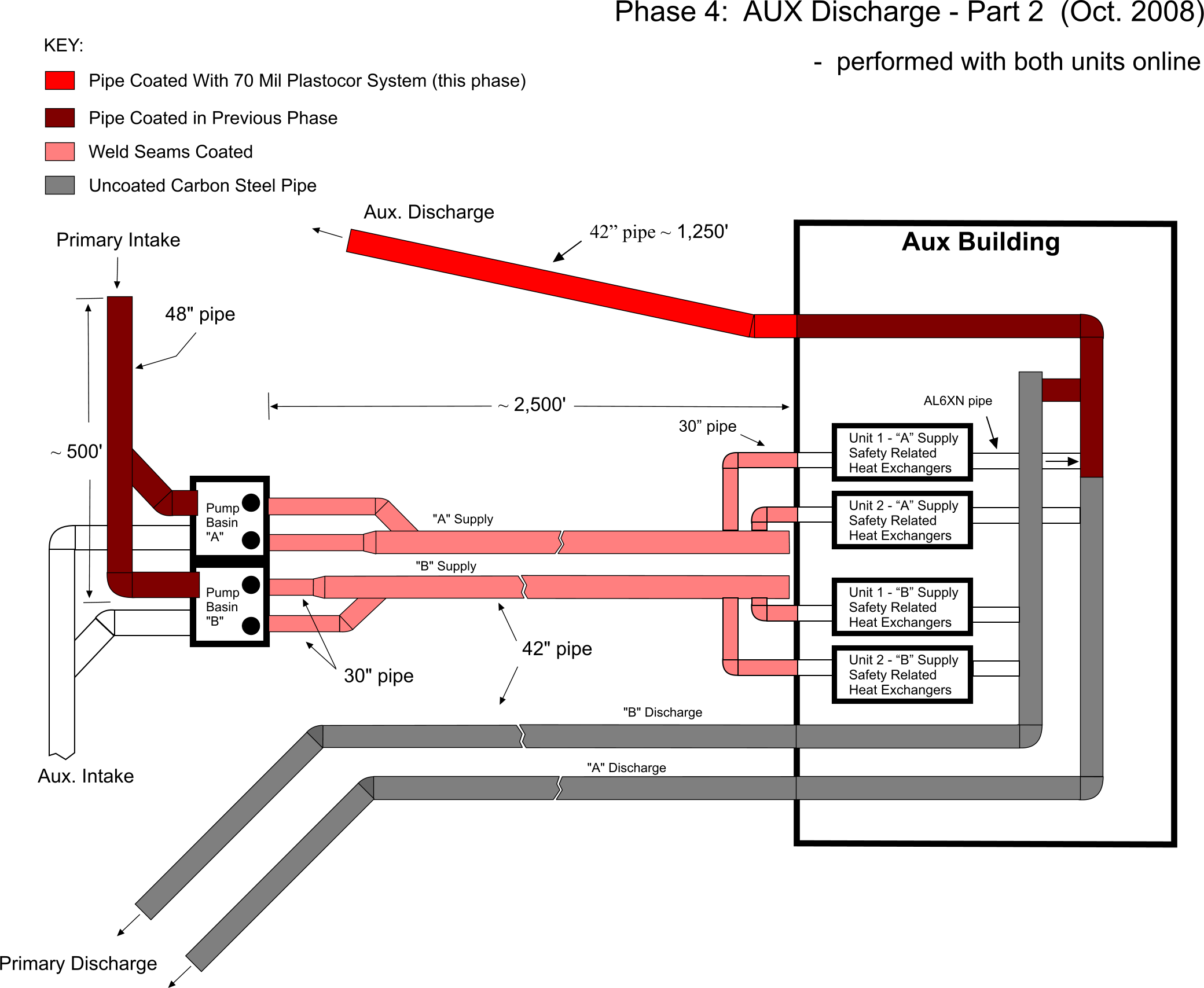
Phase 4 (October 2008): During this phase, 1,250′ of 42″ diameter pipe was coated while both units were online. This was the remaining uncoated part of the auxiliary discharge line located outside of the Aux Building.
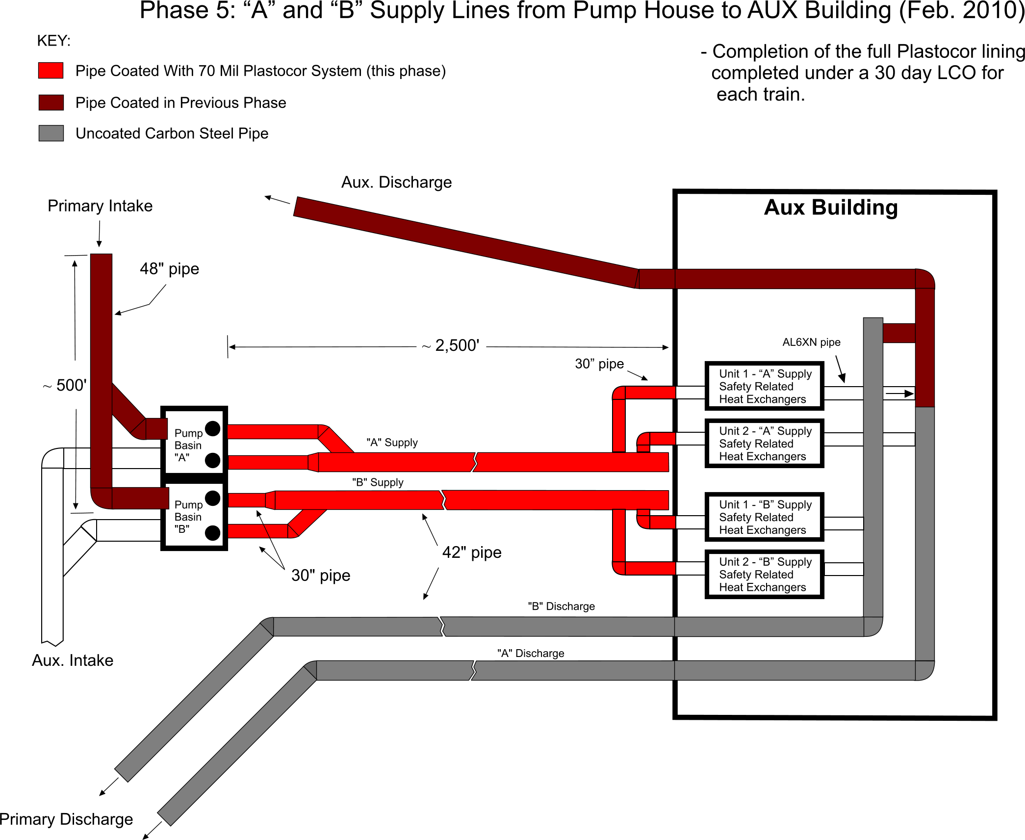
Phase 5 (February 2010): The full Plastocor lining system was installed in the Alpha and Bravo supply lines. Each train was completed during a separate 30 day LCO. (Note: The weld seams of these pipes had been previously coated during Phase 2, four years earlier.)
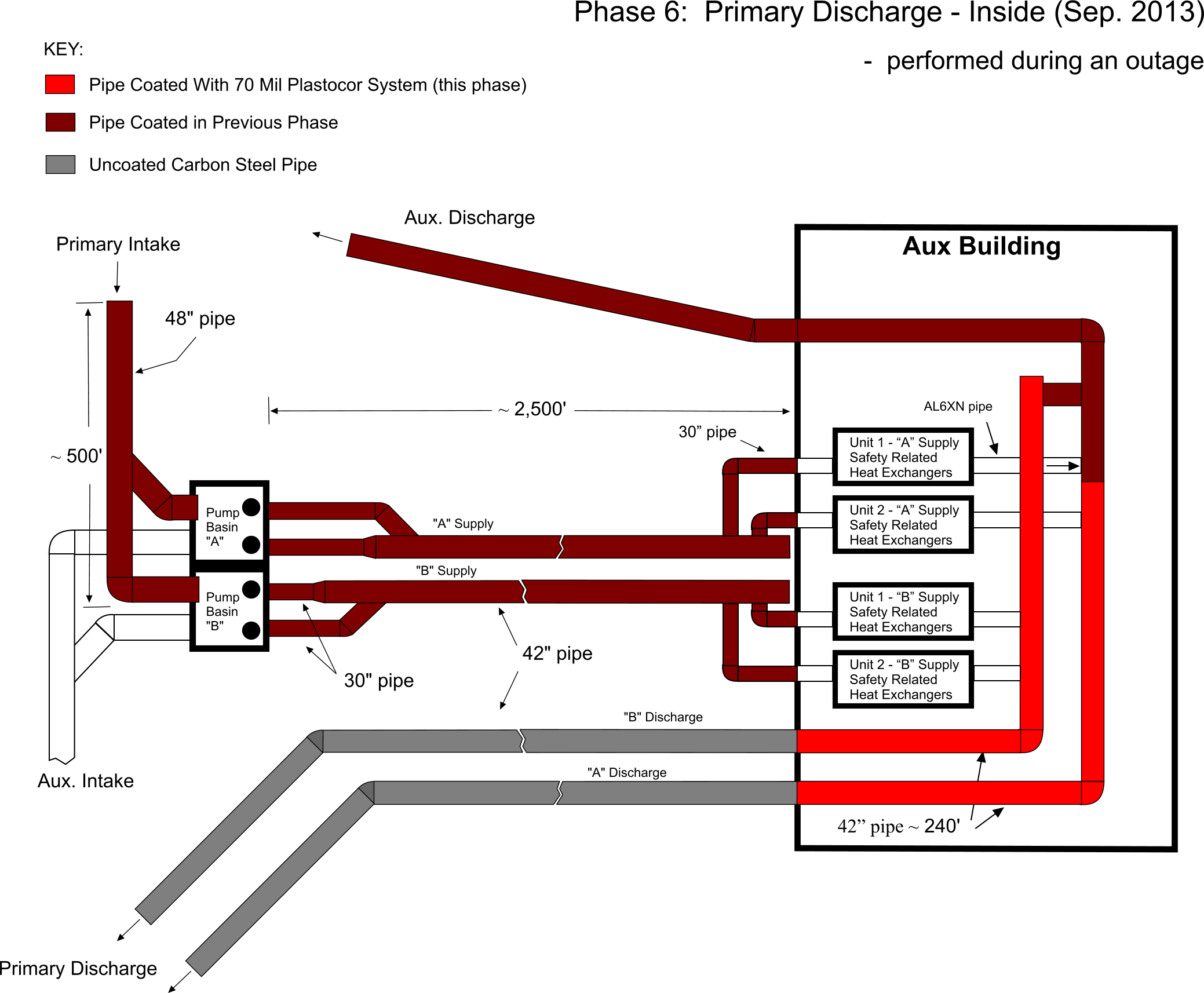
Phase 6 (September 2013): During this phase the primary discharge pipe located within the Aux building was coated. The scope was 240′ of 42″ pipe and was performed during an outage.
Project Phases – Timeline 2005 to Present
Project Photos:

In order to dewater the intake pipe to the pump house, a coffer dam was constructed at the lake intake located. Barges were anchored from the shore to the coffer dam to provide an access bridge.
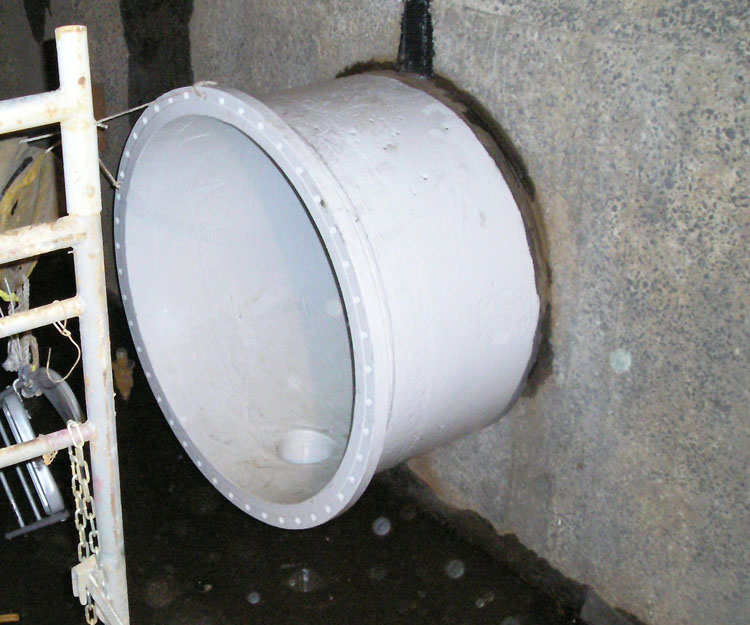
First Coat to Supply Pipe at Pump House Basin
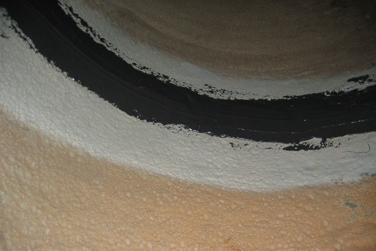
Circumferential Weld Coating (Phase 2). During this Phase, just the welds were coated to prevent further deterioration.

Coated Supply Pipe with Access Carts.

Final Coat to Supply Pipe at Alpha/Bravo Split.
Second Coat Applied to the Supply Pipe.

Circumferential and Linear Weld Coating (Phase 2). Four year later, the full Plastocor lining was applied to the rest of the pipe interior.
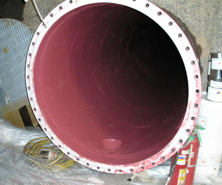
Coated Supply Pipe